basic Functionality
The linear guide and the camera car
The Control Unit
The Motor Driver
The Protocoll
basic Functionality
The cam drive controller sends serial data to the motor driver, which is also the trigger electronics for the camera, so only one cable to the camera car is necessary.
The communication interface is designed so that it is possible to expand more axes of motion.
 (concept)
The linear guide and the camera car
Photos:


Partlist:
| Schrittmotor | 1 Stk. NEMA 23 Baugröße(57 x 57mm) 1.8° Schrittwinkel |
| Getriebe | 1Stk. Getriebe 4Nm 50:1 |
| Getriebe-Adaptersatz | 1 Stk. ADAPTOR KIT C |
| Zahnriemen T5 | 300cm PU-Zahnriemen Profil T5 Breite 10mm Meterware 10 T5 (Polyurethan mit Stahl-Zugstrang) |
| Klemmplatte | 2 Stk. Klemmplatte aus AL für Zahnriemen Profil T5 Riemenbreite 10mm |
| Zahnriehmenrad | 1 Stk. T5 27 Zähne für Riemenbreite 10mm 21 T5/27-2 |
| Linearführung | L=xxx mm |
| Diverses |
2x AL-Platten 200x180x2mm |
The Control Unit
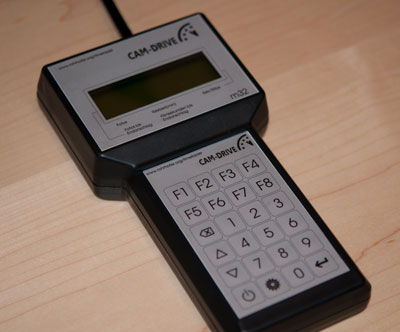
The control unit includes a variety of time-lapse applications, the 20x4 LC-Display and a keypad.
The source code is written in Bascom and available on request.
Circuit diagram Control Unit:

rev0.9
the motor driver
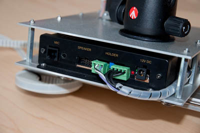
first Prototype
The motor driver consists of a stepper motor controller and trigger electronics for the camera.
Circuit diagram motor driver:

rev0.9
the protocol
The protocol is designed for universal and is using a serial connection,to control a variety of motion axes.
The first char is sent in to set the function, after which the next chars, up to 4 digits, defines the parameter values.
examples:
"R100" 100 steps to the right moves
"L84" turn left 84 steps
"F140" sends the focus signal 140ms long to the Camera
"S50", the trigger signal is sent 50 ms long to then Camera
Further axes are contemplated that instead of "R" right - should be used "L" left, for example, "A" & "B" stands for an another axis.
Comments powered by CComment