Here comes a tutorial for the mydata converter, please note that it is not ready for this time.
1. GUI description - Main Form
1.1. GUI description - ASCii import Form
1.2. GUI description - ODB++ import Form
2. ASCii import Form
2.1. Open your file
2.2. Name the PCB
2.3. Set up reference points
2.4. Import settings
3. ODB++ import Form
3.1. open your file
3.2. select top or bottom side
4. Preview and edit importdata
4.1. Mirror X or Y axis
4.2. Rotate all parts
4.3. Replace / Replace all
4.3.1. Import components from your machine
4.3.2. use Replace / Replace all
4.4. Set part as reference point
4.5. Set mount skip on all parts
5. Project settings
6. Preview
7. Export
8. Import in TPSYS
9. Special Tweaks
9.1. create your own set of standard values
1. GUI description - Main Form
The CadConverter starts with following main form.
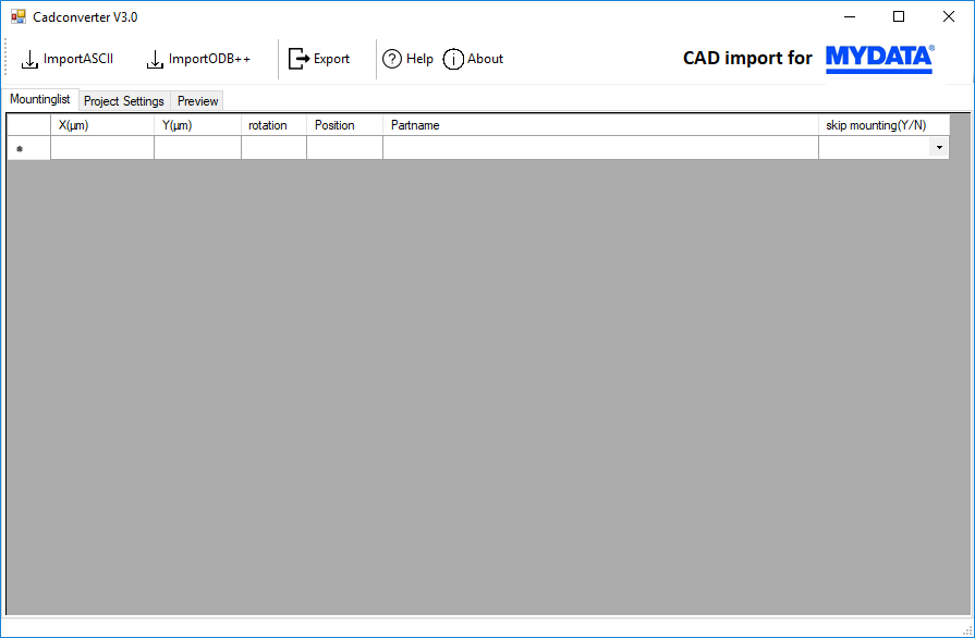
Here you can open the import dialogs and export the imported data to an machine readable format.
Further you can edit the imported data, set the project parameter and preview the pick and place positions.
1.1. GUI description - ASCii import Form
With a click on the ImportAscii button in the Main form the Ascii import dialog shows up.
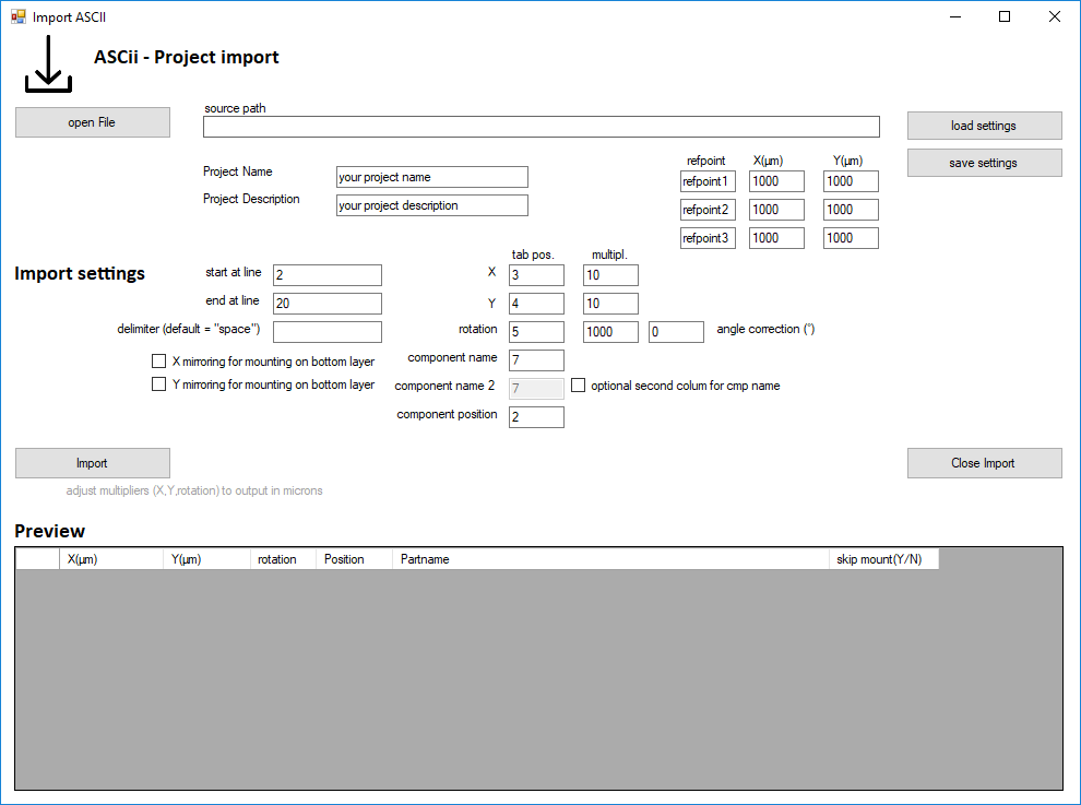
Here you can set all parameters to import pick and place data from a ascii file.
You also can save and load a set of parameters.
1.2. GUI description - ODB++ import Form
With a click on the ImportOSB++ button in the Main form the ODB++ import dialog shows up.
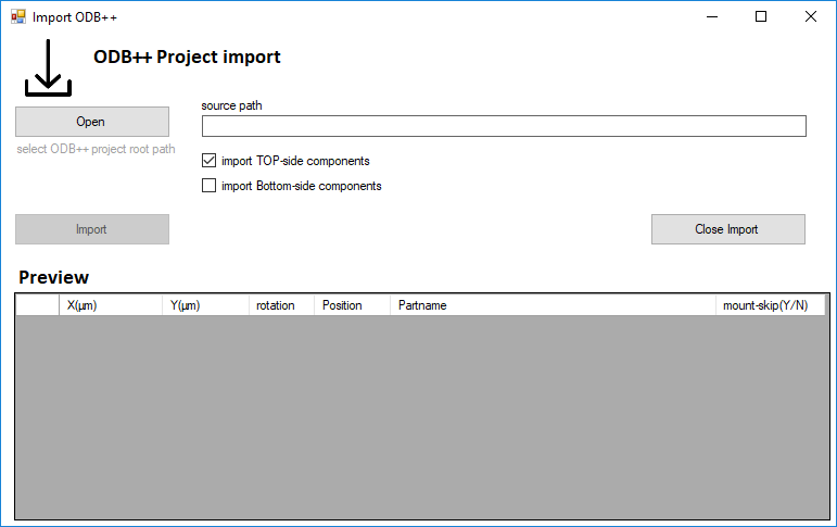
Since ODB ++ is a defined standard, it is sufficient to specify the project path here.
You can choose if you want to import the top or bottom pick&place data.
2. ASCii import Form
2.1. open your file
Use the "open file" button and open the file that contains the XY placment data from your developers cad programm.
Note:
Some CAD programs export the comma as a dot ".", be sure that it is a ',' and be sure that the tab delimiter is an other character!
If not, you can correct this easily with MS Excel. Just import the file as txt/csv and "search and replace" all dots with a "," and save it as a ".csv" file. Sometimes Excel converts some coordinates into a date format please, check this also.
2.2. Name the PCB
Fill in the Name and description in the "Project Name" and " Project Description" field.
Attention! Do not use names longer than 35 characters ! The import will not work with longer names.
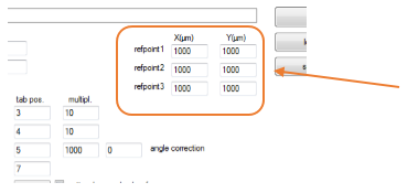
2.3. Set up to 3 reference points
Take 2 or 3 reference points anywhere on your board and take the coordinates of these points from your developer CAD (The best way is to look in the gerber files of your board!).
Please note: It doesn't matter where the X0 Y0 Point of your CAD data is.
Example:
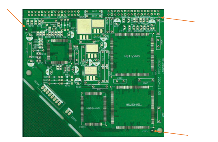
Find the coordinates of the reference point in your CAD-Program and enter it in the „refpoint“ fields.
Just remember that you have to manually find/teach the reference points the first time on your machine, because the machine otherwise messes up all of your coordinates.
2.4. Fill in your import settings
which are:
- the start / end line in your previus opend file.
- set the delimiter of your file (standard is "space")
- the tab positions of the necessary coordinates and Partnames and if the data isn't provided as a µm, then you can set a multiplier to correct them.
If you entered it press "Import"

3. ODB++ import Form
3.1. open your file
Use the "open file" button and open the folder "odb" that contains the poject data.
Note:
Some CAD programs export the odb data as .zip file. Be sure that you unzipped it!
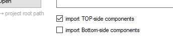
3.2. select top or bottom side
Use the checkbox to select witch side of the ocb you want to import
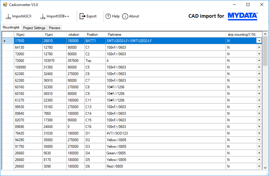
4. Preview and edit importdata
After you have importet you pick&place mounting list you can review it in the "Mountinglist" Tab.
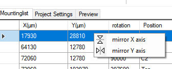
4.1. mirror X or Y axis
Right-click on any data in the X or Y column to show the manipulator.
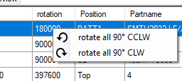
4.2. Rotate all parts
Right-click on any data in the rotation column to show the manipulator.
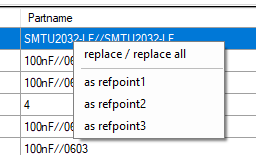
4.3. Replace / Replace all
Right-click on any data in the partname column to show the manipulator.
4.3.1. Import components from your machine
Before you can use the replace / replace all feature, you must first load your created components from your placement machine.
To use this feature please export all components from your machine and place the file as "cmp.cmp" in the same folder where the MYDATA-Cadconverter is located.
Here are some screenshots from the machine:
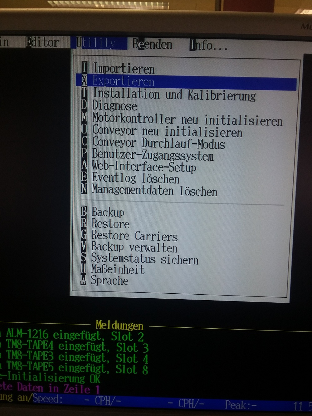
(X) for Export
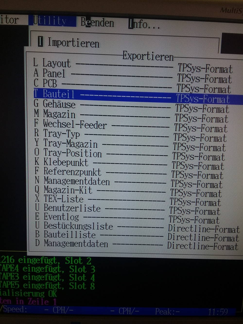
(T) for components
Use "Crtl+A" to select all of your components!
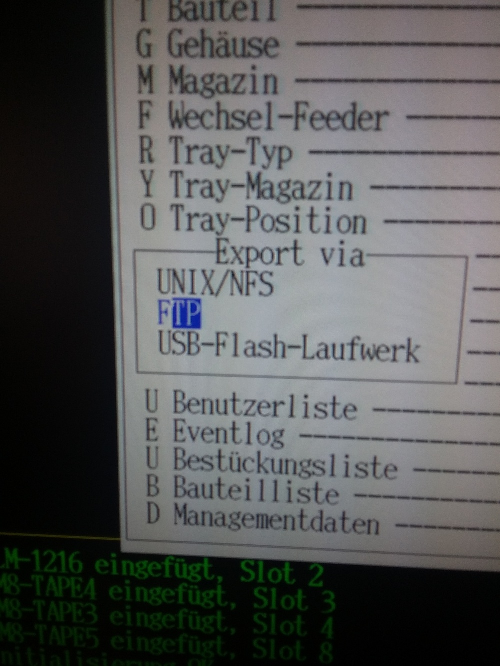
Save the file as "cmp.cmp" and place it in the MYDATA Cad Converter directory.
4.3.2. Replace / Replace all
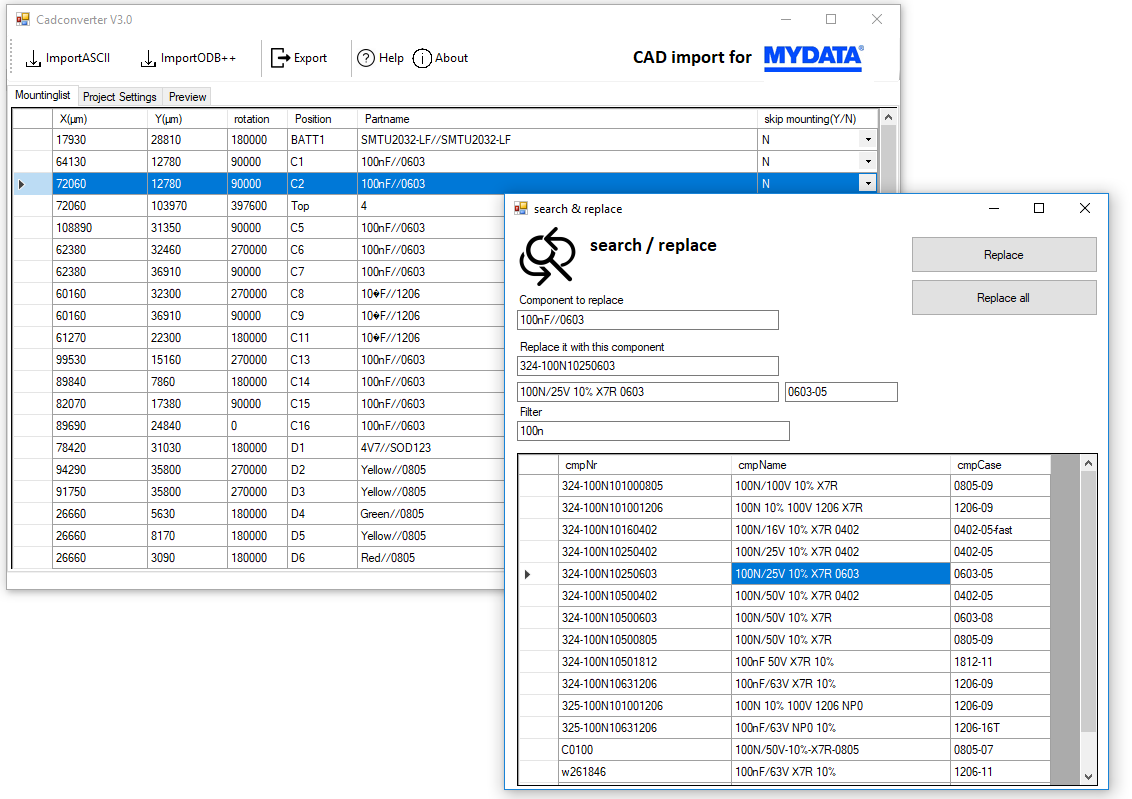
- Click on the Search and Replace Button and the "Serach and Replace Components" window opens.
- Double Click on the Partname will add this component in the "Component to replace" textbox.
- Click on the cmpNr or cmName on your partlist will add it to the "Replace it with this component"
To find your component quickly you can enter a search phrase in the "filter" textbox.
- Finnaly you can replace the partname you have clicked in the main window by click on the "Replace" button. Or you can replace all partnames that are similar in the main window by clicking on the "Replace all" button.
4.4. Set part as reference point
Right-click on any data in the partname column to show the manipulator.
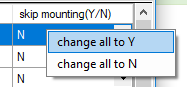
4.5. Set mount skip on all parts
Right-click on any data in the partname column to show the manipulator.
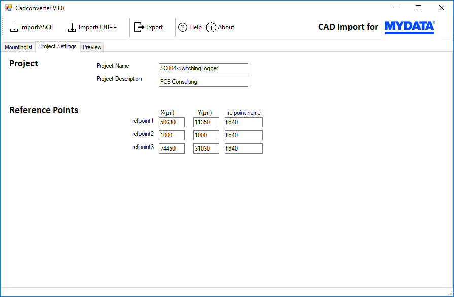
5. Project settings
With a click on the project settings tab you can give your project a name and you can setup the reference points.
If you're not sure how to set up reference points look at chapter 2.3 setp up reference points
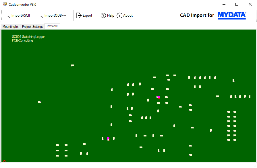
6. Preview
With a click on the preview tab you can do a quick check if your placementdata is correct.
7. Export
Finaly, if you ready press "Export" and your conversion is ready to import on you mydata pick and place machine!
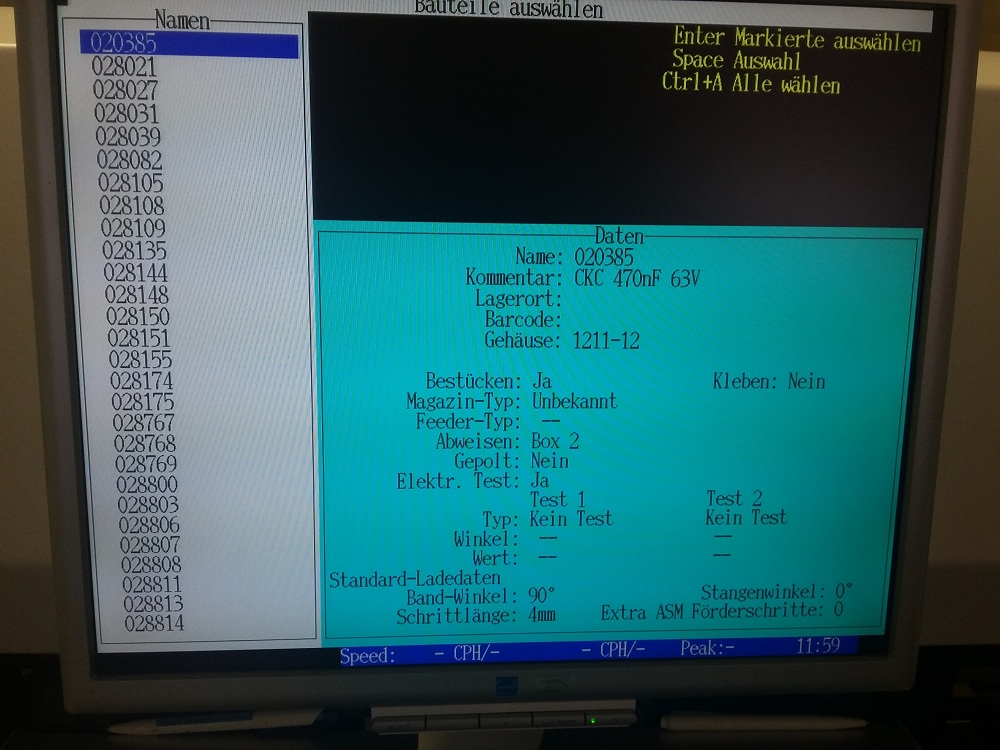
8. Import in TPSYS
Follow these steps on your machine:
The screenshots are unfortunately in German language, I hope you can see how the import will still work


And then follow the instructions on your machine.
Just remember that you have to manually find/teach the reference points the first time on your machine, because the machine otherwise messes up all of your coordinates.
9. Special tweaks
9.1. create your own set of standard values
And for your request for individual standard settings i have following solution. ->
Now you can save a normal set of settings with the usual button in the ascii import dialog.
But if you save this set with following name "standards.ini" in the programm path it will load allways this set as standard values.
Comments powered by CComment